Experiment 6: Transient Behavior Analysis
Team Report Due: Fri. 4/30
Abstract
- Introduction
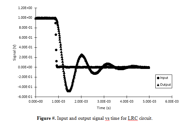
In this experiment, transient system behavior is investigated for both first- and second-order systems. Two types of first-order systems are investigated: thermal and electrical. In the thermal system, the transient response of a thermocouple is examined. For the electrical system, a resistor-capacitor (RC) circuit (see Experiment #5) is examined. For the second-order system, a single system is investigated: an inductor-resistor-capacitor (LRC) circuit.
In each of the three systems, a step input is used for excitation to investigate the transient responses. For each system, the transient behavior is measured experimentally and used to determine time domain parameters which quantify the transient behavior; these include the time constant, rise time, maximum overshoot percentage, peak time, and settling time. For the first order systems, the system’s time constant and frequency bandwidth are also estimated.
2. Theory
3. Methods
5. Discussion
Important. (regarding audience of the report)
The audience of this report is intended for a bright mechanical engineering student who is just finished a course in Mechanical Vibrations and Control Systems. The audience is familiar with the terms: natural frequency, damped natural frequency, damping ratio, logarithmic decrement, and a mass-spring-damper system.
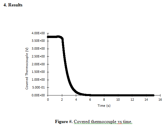
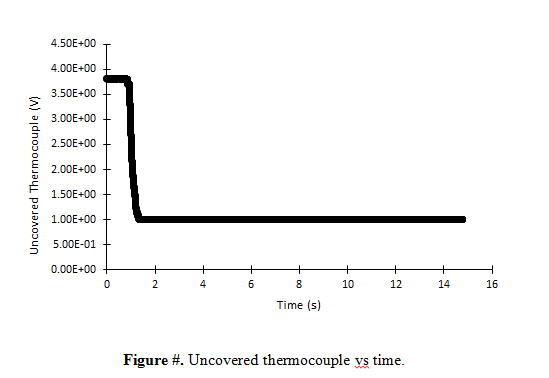
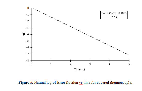
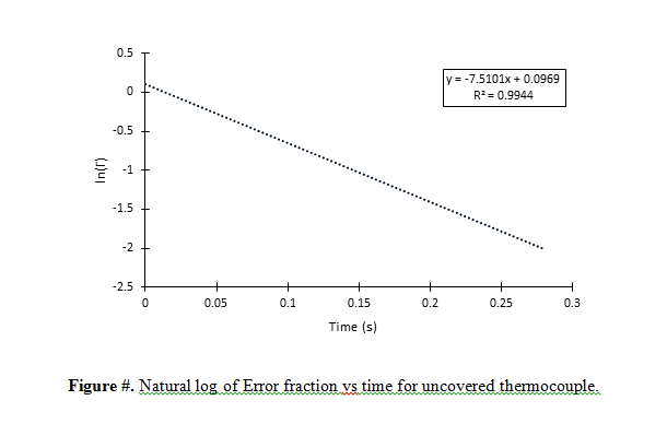
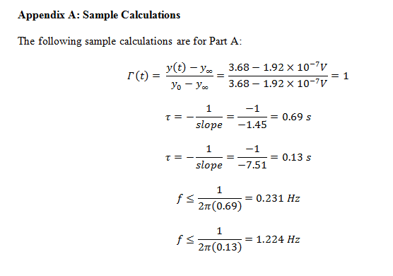
Part A: Thermal System Transient Response
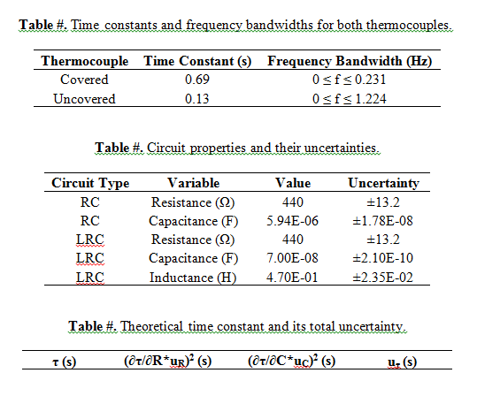
1. Discuss how you determined the range of data that was used to measure the time constants for the thermocouples. How important is it to select the appropriate range of data, i.e. how does it affect your results? 2. Discuss the differences of the time constants and how this relates to their bandwidth. Compare the covered to the uncovered thermocouple and if they are different, explain why.
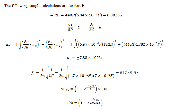
Part B: Electrical System Transient Response
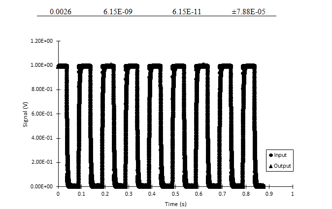
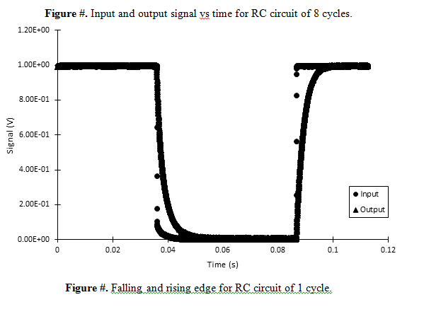
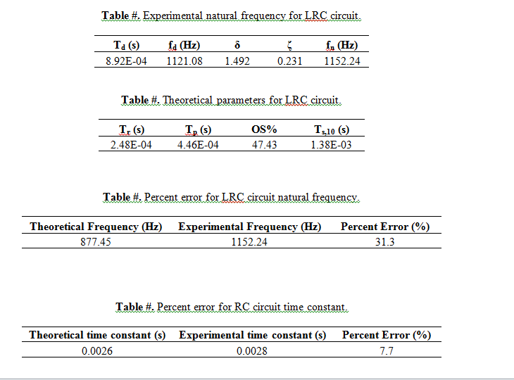
1. (RC circuit) Compare (% error) the experimental time constants for falling and rising edges. How did you predict they would compare? Compare (% error) and discuss the differences between the theoretical and average experimental time constants (average the time constants for the falling edge and rising edge). Are your experimental values within uncertainty bounds?
Page 16 of 17
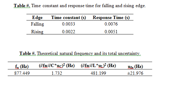
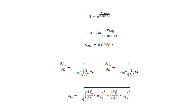
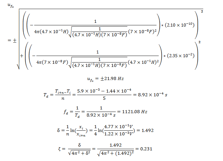
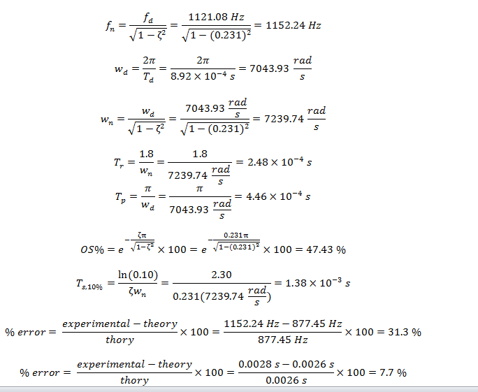
2. (LRC circuit) Compare (% error) and discuss the differences between the theoretical and experimental natural frequencies of the system. Are your experimental values within the uncertainty bounds?
3. (LRC circuit) If the damping in the system is suddenly half of its original value, what is the effect of on the system’s output signal with time?
6. Conclusion
7. References
Appendix B: Extra Figures/Tables
Appendix C: Contributions
If you need answers to this assignment, WhatsApp/Text +1 646 978 1313 or send us an email to admin@shrewdwriters.com and we will reply instantly. We provide original answers that are not plagiarized, please try our service.
Leave a Reply